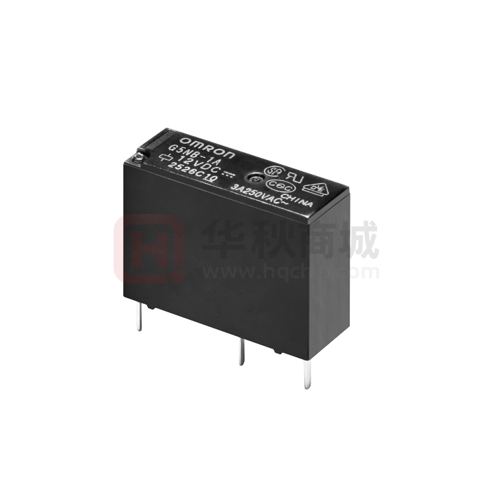
G5NB
PCB Power Relay
A Miniature Relay with 1-pole
3A/5A Switching Capability and
10 kV Impulse Withstand Voltage
• Highly efficient magnetic circuit for high sensitivity (200 mW).
• Small, yet provides 10-kV impulse withstand voltage (between coil
and contacts).
• Standard model conforms to UL/CSA/VDE standards.
• Satisfies EN61010 reinforced insulation requirements.
• IEC/EN 60335-1 conformed. (-HA Model)
RoHS Compliant
■Model Number Legend
■Application Examples
•
•
•
•
•
G 5 N B -@ @ @- @- @ -@
——— — — —
1 2 3
4
5
1. Number of Poles
1: 1-pole
2. Contact Form
A: SPST-NO (1a)
3. Enclosure rating
None: Flux protection
4 : Sealed
6
4. Classification
None : Standard
E : High-capacity
Water heaters
Refrigerators
Air conditioners
Home appliances
Small electric appliances
G
5
N
B
5. Market Code
None : General purpose
HA : Home Appliance according
to IEC/EN60335-1
6. Packing
None : Tray Packing
SP : Tube packing
■Ordering Information
Terminal Shape Market Code
PCB terminals
General
purpose
Home
Appliance
Classification
Contact form
Standard
SPST-NO (1a)
High-capacity
Enclosure rating
Flux protection
Sealed
Flux protection
Sealed
Model
G5NB-1A (-SP)
G5NB-1A4 (-SP)
G5NB-1A-E (-SP)
G5NB-1A4-E (-SP)
Flux protection
G5NB-1A-E-HA (-SP)
Rated coil voltage Minimum packing unit
5VDC
12VDC
18VDC
24VDC
100 pcs/Tray
(50 pcs/tube)
12VDC
24VDC
Note. When ordering, add the rated coil voltage to the model number.
Example: G5NB-1A DC5
Rated coil voltage
However, the notation of the coil voltage on the product case as well as on the packing will be marked as @@VDC.
1
�G5NB
PCB Power Relay
■Ratings
●Coil
Item
Rated voltage
5 VDC
12 VDC
18 VDC
24 VDC
Rated current
(mA)
Coil resistance
(Ω)
40
16.7
11.1
8.3
125
720
1,620
2,880
Must operate voltage Must release voltage
(V)
(V)
% of rated voltage
75% max.
10% min.
Max. voltage
(V)
Standard:
180% (at 23°C)
High-capacity:
170% (at 23°C)
Power consumption
(mW)
Approx. 200
Note 1. The rated current and coil resistance are measured at a coil temperature of 23°C with a tolerance of ±10%.
Note 2. The operating characteristics are measured at a coil temperature of 23°C.
Note 3. The “Max. voltage” is the maximum voltage that can be applied to the relay coil.
●Contacts
Item
Resistive load
Load
Standard
Contact Type
Contact material
3 A at 125 VAC
3 A at 30 VDC
3A
Rated load
Rated carry current
Max. switching voltage
Max. switching current
G
5
N
B
High-capacity
Single
Ag-alloy (Cd free)
5 A at 250 VAC
3 A at 30 VDC
5A
250 VAC, 30 VDC
3A
■Characteristics
Contact resistance *1
Operate time
Release time
Insulation resistance *2
Between coil
and contacts
Dielectric
Between
strength
contacts of the
same polarity
Impulse
Between coil
withstand
and contacts
voltage
Vibration
resistance
Destruction
Malfunction
Shock
resistance
Destruction
Malfunction
Mechanical
Durability
Electrical
(resistive load)
Failure rate (P level)
(reference value) *3
Ambient operating
temperature *4
Ambient operating humidity
Weight
100 mΩ max.
10 ms max.
10 ms max.
1,000 MΩ min.
4,000 VAC, 50/60 Hz for 1 min
750 VAC, 50/60 Hz for 1 min
10 kV (1.2 x 50 μs)
10 to 55 to 10 Hz, 0.75 mm single amplitude
(1.5 mm double amplitude)
10 to 55 to 10 Hz, 0.75 mm single amplitude
(1.5 mm double amplitude)
1,000 m/s2
100 m/s2
5,000,000 operations min.
Standard (G5NB-1A, -1A4)
200,000 operations at 125 VAC, 3A
200,000 operations at 30 VDC, 3A
High-capacity (G5NB-1A-E, -1A4-E)
100,000 operations at 250 VAC, 5A
200,000 operations at 30 VDC, 3A
(with a rated load at 1,800 operations/hour)
DC5V 10mA
-40°C to 85°C
(with no icing or condensation)
5% to 85%
Approx. 4 g
Note. Values in the above table are the initial values at 23°C.
*1. Measurement conditions: 5 VDC, 1 A, voltage drop method
*2. Measurement conditions: Measured at the same points as the dielectric
strength using a 500 VDC ohmmeter.
*3. This value was measured at a switching frequency of 120 operations/min.
*4. Sealed (G5NB-1A4, -1A4-E): -40°C to 70°C
2
5A
■Actual Load Life (Reference Values)
1. 120 VAC motor and lamp load
2.5A surge and 0.5A normal:
250,000 operations min. (at 23°C)
2. 160 VDC valve load (with varistor)
0.24A:
250,000 operations min. (at 23°C)
3. 140 VAC pump load
Inrush: 5.4 A (o-p), Steady state: 1.6 A
200,000 operations min. (Ambient temperature: 23°C)
4. 100 VAC motor load
Inrush: 10.7 A (o-p), Steady state: 1.1 A
200,000 operations min. (Ambient temperature: 23°C)
�G5NB
PCB Power Relay
■Engineering Data
●Maximum Switching Capacity
Standard models
High-capacity models
10
3
Switching current (A)
Switching current (A)
AC resistive
load
AC resistive
load
DC resistive
load
1
DC resistive
load
0.1
1
10
30
100
250
1,000
Switching voltage (V)
Switching voltage (V)
●Durability
Standard models
High-capacity models
100
G
5
N
B
Durability (x 104 operations)
Durability (104 operations)
125 VAC, 30 VDC resistive load
50
30
10
5
3
30VDC resistive load
250VAC resistive load
1
0
1
2
3
4
Switching current (A)
Switching current (A)
●Ambient Temperature vs. Maximum Coil Voltage
Standard models
High-capacity models
Unconfirmed
area
200
220
Test item: G5NB-1A, 24 VDC
Number of Relays: 5 pcs
Uncon-
3A current
180
160
140
120
100
Maximum coil voltage (%)
Maximum coil voltage (%)
220
Test Item: G5NB-1A-E,24 VDC
Number of Relays: 5 pcs
200 firmed
5A current
area
180
160
140
120
100
80
80
0
20 23
40
60
80 85
Ambient temperature (°C)
100
0
20 23
40
60
80 85
100
Ambient temperature (°C)
Note: The maximum coil voltage refers to the maximum value in a varying range of operating power voltage, not a continuous voltage.
3
�G5NB
PCB Power Relay
●Shock malfunction
Standard models
Y
1,000
Y
1,000
Energized
De-energized
700
1,000
X
High-capacity models
Test Item: G5NB-1A, 24VDC
Number of Relays: 5 pcs
1,000
Z'
1,000
X
Test Method: Shock was applied 3
times in 6 directions along 3 axes
and the level at which shock caused
malfunction was measured.
Energized
De-energized
700
Test Item: G5NB-1A-E, 24VDC
Number of Relays: 5 pcs
1,000
Z'
Test Method: Shock was applied 3
times in 6 directions along 3 axes
and the level at which shock caused
malfunction was measured.
Rating: 100 m/s2
Rating: 100 m/s2
125
125
X'
1,000
Z
1,000
1,000
Y'
X'
1,000
Z
1,000
1,000
Y'
Unit: m/s2
Shock direction
X
X'
Y
Z
Z'
Y'
Unit: m/s2
Shock direction
X
X'
Y
Z
Z'
Y'
■Dimensions
(Unit: mm)
G G5NB-1A(4)(-E), G5NB-1A-E-HA
5
N
B
PCB Mounting Holes
(Bottom View)
Tolerance: ±0.1 mm
7.2max.
(7.0)*
20.5max.
(20.4)*
Terminal Arrangement/
Internal Connections
(Bottom View)
(1.05)
11.5
15.3max.
(15.0)*
(1.15)
7
Four, 1.1 dia.
1
2
3
4.7
4
3.4
@0.4
0.27
11.5
0.33
7
(No coil polarity)
0.8
4.7
*Average value
4
�G5NB
PCB Power Relay
■Approved Standards
The approval rating values for overseas standards are different from the performance values determined individually. Confirm the values
before use.
●UL Recognized:
CSA Certified:
Model
(File No. E41515)
(File No. LR31928)
Contact form
G5NB-1A(4)
Coil ratings
SPST-NO
(1a)
G5NB-1A(4)-E
G5NB-1A-E-HA
5~24V DC
●EN/IEC, VDE Certified
Model
100,000
3A 30V DC (Resistive) 70°C
6,000
5A 250 V AC (Resistive) 85°C
5A 30 V DC (Resistive) 70°C
6,000
Coil ratings
5, 12, 18, 24V
DC
3A 250V AC (Resistive) 85°C
3A 30V DC (Resistive) 85°C
100,000
5A 250 V AC (Resistive) 85°C
5A 30 V DC (Resistive) 85°C
10,000
3A 250V AC (Resistive) 85°C
100,000
Creepage distance
6.0 mm min.
Clearance distance
6.0 mm min.
Insulation material group
IIIa
Type of insulation coil-contact circuit
open contact circuit
Number of test
operations
Contact ratings
G5NB-1A(4)
G5NB-1A(4)-E
G5NB-1A-E-HA
3A 250V AC (Resistive) 85°C
(Certificate No. 137575)
Contact form
SPST-NO
(1a)
Number of test
operations
Contact ratings
G
5
N
B
Pollution degree 2 / Reinforced (Sealed)
Pollution degree 3 / Basic (Flux protection) / Reinforced (Sealed)
Micro disconnection
Rated Insulation voltage
250 V
Pollution degree
3
Rated voltage system
250 V
Over voltage category
III
Category of protection according to IEC 61810-1
RT II (Flux protection) / RT III (Sealed)
Glow wire according to IEC 60335-1
GWT 750°C min. (IEC 60695-2-11) / GWFI 850°C min. (IEC 60695-2-12)
Tracking resistance according to IEC 60112
PTI 250 V min. (housing parts)
Flammability class according to UL94
V-0
■Precautions
●Please refer to “PCB Relays Common Precautions” for correct use.
• Application examples provided in this document are for reference only. In actual applications, confirm equipment functions and safety before using the product.
• Consult your OMRON representative before using the product under conditions which are not described in the manual or applying the product to nuclear control systems, railroad
systems, aviation systems, vehicles, combustion systems, medical equipment, amusement machines, safety equipment, and other systems or equipment that may have a serious
influence on lives and property if used improperly. Make sure that the ratings and performance characteristics of the product provide a margin of safety for the system or
equipment, and be sure to provide the system or equipment with double safety mechanisms.
Note: Do not use this document to operate the Unit.
OMRON Corporation
Electronic and Mechanical Components Company
Contact: www.omron.com/ecb
Cat. No. J143-E1-11
0117(0207)(O)
5
�


 工商网监
湘ICP备2023018690号
工商网监
湘ICP备2023018690号
